Datasheet4U Logo Datasheet4U.com

BH6150F

System reset

BH6150F Features

* Two types of reset circuit provided. 1) Reset circuit 1 (input voltage detector) Detection voltage: 1.25V (Typ.) Transmission delay time: 200µs (Typ.) Open collector output, and 10kΩ pull-up resistor on chip. 2) Reset circuit 2 (supply voltage detector) Detection voltage: 4.2V (Typ.) Trans

BH6150F General Description

Pin No. 1 2 3 4 5 6 7 8 Pin name Ct0 Input Ct1 GND Output 2 Output 1 VCC Manual reset Delay time control∗ Reset circuit 1 input Delay time control∗ GND Reset circuit 2 output Reset circuit 1 output Power supply Manual reset input Function ∗ When neither Ct0 or Ct1 are connected, the delay time is .

BH6150F Datasheet (78.19 KB)

Preview of BH6150F PDF

Datasheet Details

Part number:

BH6150F

Manufacturer:

ROHM ↗

File Size:

78.19 KB

Description:

System reset.
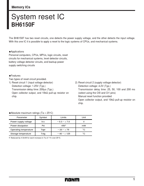
Memory ICs System reset IC BH6150F The BH6150F has two reset circuits, one detects the power supply voltage, and the other detects the input voltage..
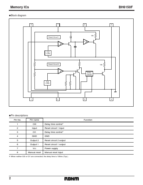
📁 Related Datasheet

BH6111FV Power-unit (Rohm)

BH6113FV Power-unit (Rohm)

BH6114FV Power-unit (Rohm)

BH616UV1610 Ultra Low Power/High Speed CMOS SRAM (Brilliance Semiconductor)

BH616UV1611 Ultra Low Power/High Speed CMOS SRAM (Brilliance Semiconductor)

BH616UV4010 Ultra Low Power/High Speed CMOS SRAM 256K X 16 bit (Brilliance Semiconductor)

BH616UV8010 Ultra Low Power/High Speed CMOS SRAM (Brilliance Semiconductor)

BH616UV8011 Ultra Low Power/High Speed CMOS SRAM (Brilliance Semiconductor)

BH6172GU System Regulator (Rohm)

BH6173GUL Silicon Monolithic Integrated Circuit (Rohm)

TAGS

BH6150F System reset Rohm

Image Gallery

BH6150F Datasheet Preview Page 2 BH6150F Datasheet Preview Page 3

BH6150F Distributor