Datasheet Details
| Part number | TB6562ANG |
|---|---|
| Manufacturer | Toshiba ↗ Semiconductor |
| File Size | 415.86 KB |
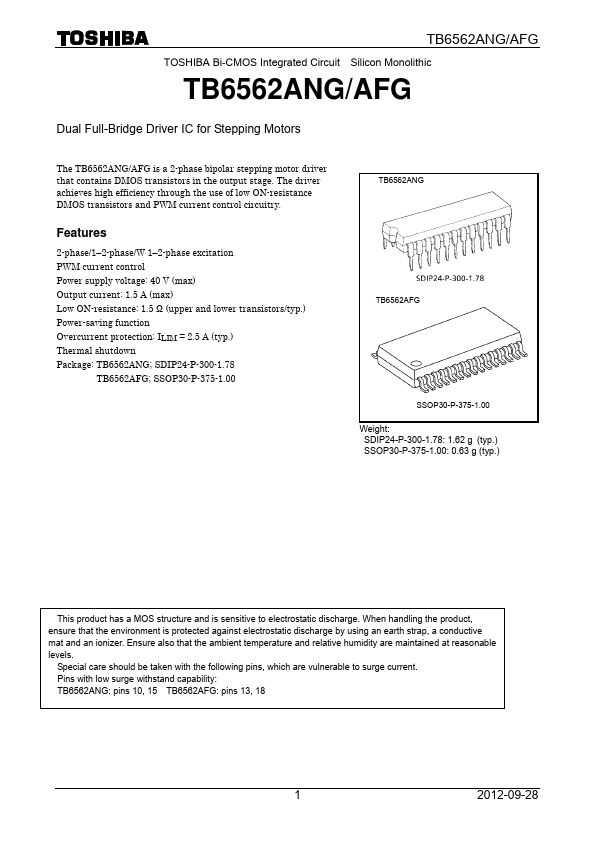
| Description | Dual Full-Bridge Driver |
| Datasheet |
 TB6562ANG_ToshibaSemiconductor.pdf TB6562ANG_ToshibaSemiconductor.pdf
|
| Part number | TB6562ANG |
|---|---|
| Manufacturer | Toshiba ↗ Semiconductor |
| File Size | 415.86 KB |
| Description | Dual Full-Bridge Driver |
| Datasheet |
TB6562ANG_ToshibaSemiconductor.pdf
|
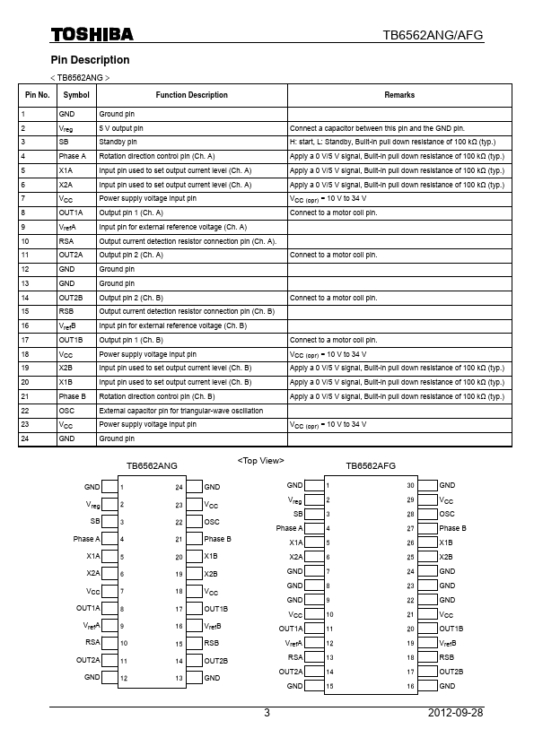
< TB6562ANG > Pin No.Symbol Function Description Remarks 1 GND Ground pin 2 Vreg 5 V output pin 3 SB Standby pin Connect a capacitor between this pin and the GND pin.H: start, L: Standby, Built-in pull down resistance of 100 kΩ (typ.) 4 Phase A Rotation direction control pin (Ch.A) Apply a 0 V/5 V signal, Built-in pull down resistance of 100 kΩ (typ.) 5 X1A Input pin used to set output current level (Ch.A) Apply a 0 V/5 V signal, Built-in pull down resistance of 100 kΩ (ty
📁 TB6562ANG Similar Datasheet