Datasheet Details
| Part number | TB6561FG |
|---|---|
| Manufacturer | Toshiba ↗ |
| File Size | 234.60 KB |
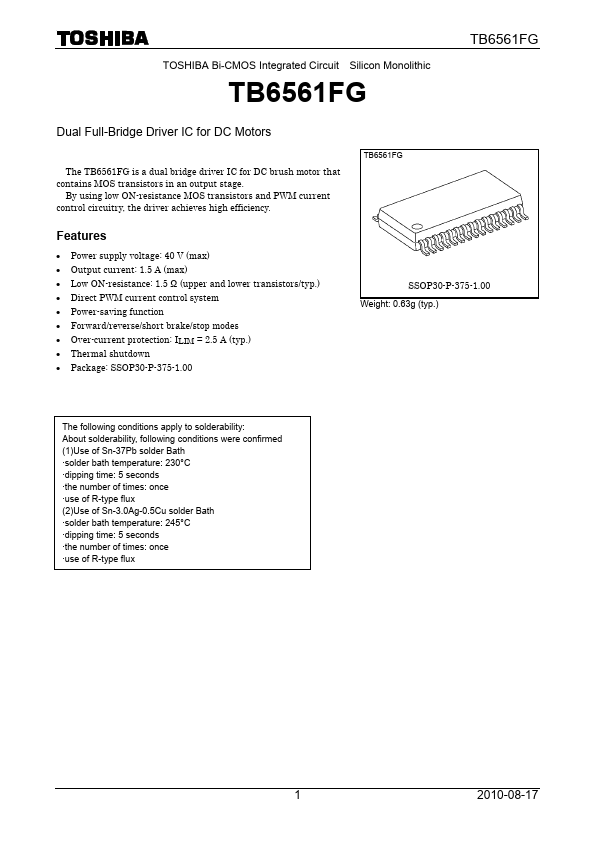
| Description | Dual Full-Bridge Driver IC |
| Datasheet |
 TB6561FG-Toshiba.pdf TB6561FG-Toshiba.pdf
|

| Part number | TB6561FG |
|---|---|
| Manufacturer | Toshiba ↗ |
| File Size | 234.60 KB |
| Description | Dual Full-Bridge Driver IC |
| Datasheet |
TB6561FG-Toshiba.pdf
|
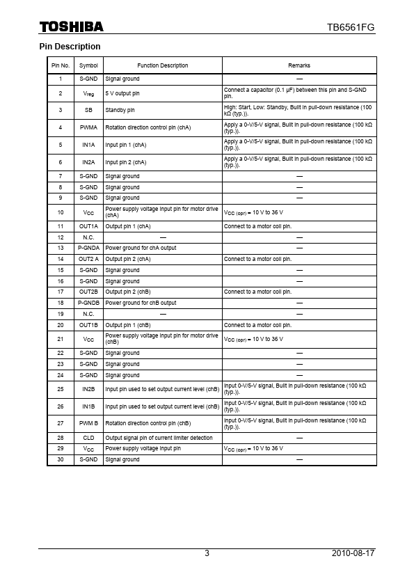
TB6561FG Pin No.Symbol Function Description Remarks 1 S-GND Signal ground ⎯ 2 Vreg 5 V output pin Connect a capacitor (0.1 μF) between this pin and S-GND pin.3 SB Standby pin High: Start, Low: Standby, Built in pull-down resistance (100 kΩ (typ.)).4 PWMA Rotation direction control pin (chA) Apply a 0-V/5-V signal, Built in pull-down resistance (100 kΩ (typ.)).5 IN1A Input pin 1 (chA) Apply a 0-V/5-V signal, Built in pull-down resistance (100 kΩ (typ.)).6 IN2A Input pin
📁 TB6561FG Similar Datasheet