BF554 Overview
Key Specifications
Operating Voltage: 115 V
| Part | BF554 |
|---|---|
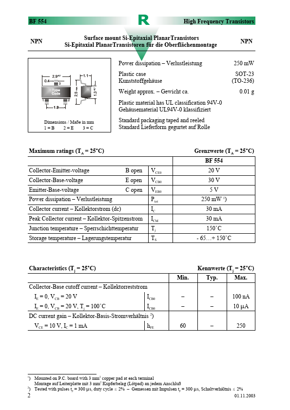
| Description | Surface mount Si-Epitaxial PlanarTransistors |
| Category | Transistor |
| Manufacturer | Diotec Semiconductor |
| Size | 160.20 KB |
Operating Voltage: 115 V
| Seller | Inventory | Price Breaks | Buy |
|---|---|---|---|
| RS (Formerly Allied Electronics) | 0 | 1+ : 40.8 USD 10+ : 38.76 USD 25+ : 36.72 USD 50+ : 34.68 USD |
View Offer |
| Newark | 0 | - | View Offer |
| Part Number | Manufacturer | Description |
|---|---|---|
| BF554 | Siemens Semiconductor Group | NPN Silicon RF Transistor |
| BF550 | Siemens Semiconductor Group | PNP Silicon RF Transistor |
| BF550 | NXP Semiconductors | PNP medium frequency transistor |
| BF556B | NXP Semiconductors | N-channel silicon junction field-effect transistors |
| BF556C | NXP Semiconductors | N-channel silicon junction field-effect transistors |