1N4448W Overview
Description
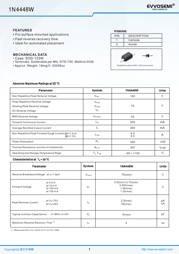
1 Cathode 2 Anode 2 1 Simplified outline SOD-123W and symbol Parameter Non-Repetitive Peak Reverse Voltage Peak Repetitive Reverse Voltage Working Peak Reverse Voltage DC Reverse Voltage RMS Reverse Voltage Forward Continuous Current Average Rectified Output Current Non-Repetitive Peak Forward Surge Current @t=1.0 μs @t=1.0 s Power Dissipation Parameter Symbols VRM VRRM VRWM VR VR(RMS) IFM IO IFSM Pd RthJA Tj, Tstg Symbols Reverse BreakdownVoltage at IR=1.0μA Forward Voltage at 5 m A at 10 m A at 100 m A at 150 m A V(BR)R VF at VR=75V Peak Reverse Current IR at VR=20V Typical Junction Capacitance f=1MHz,VR=0V Cj (1) Maximum Reverse Recovery Time trr (1)Measured with IF=IR=10mA,Irr=0.1xIR,RL=100Ω 1N4448W 100 75 53 500 250 4.0 2.0 350 357 -65 ~ +150 1N4448W 75(min) 0.62(min) 0.72(max) 0.855(max) 1.00(max) 1.25(max) 2.5(max) 25(max) 4(max) 4 Units V V V mA mA A mW °C/W °C Units V V μA nA pF ns 1 1N4448W Total Power Dissipation (mW) Fig.1 Power Derating Curve 500 400 300 200 100 0.0 25 50 75 100 125 150 175 Ambient Temperature (°C) Fig.3 Typical Instaneous Forward Characteristics 1000 100 10 TJ=25°C 1.0 0.0 0.3 0.6 0.9 1.2 1.5 1.8 2.1 2.4 Instaneous Forward Voltage (V) Junction Capacitance (pF) Instaneous Reverse Current(μA) Fig.2 Typical Reverse Characteristics 1000 100 10 TJ=25°C 1 0.1 00 20 40 60 80 100 120 percent of Rated Peak Reverse Voltage (%) Fig.4 Typical Junction Capacitance 10 TJ=25°C 1.0 0.1 0.1 1.0 10 100 Reverse Voltage (V) Instaneous Forward Current (mA) 2 1N4448W.
Key Features
- Case: SOD-123W
- Terminals: Solderable per MIL-STD-750, Method 2026
- Approx. Weight: 16mg/0.00056oz PINNING PIN