FDB9403_F085
FDB9403_F085 is N-Channel MOSFET manufactured by Fairchild Semiconductor.
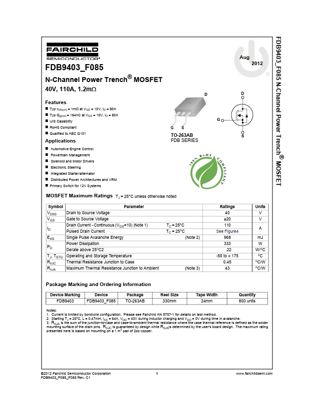
FDB9403_F085 N-Channel Power Trench® MOSFET
Aug
N-Channel Power Trench® MOSFET
40V, 110A, 1.2mΩ
Features
- Typ r DS(on) = 1mΩ at VGS = 10V, ID = 80A
- Typ Qg(tot) = 164n C at VGS = 10V, ID = 80A
- UIS Capability
- Ro HS pliant
- Qualified to AEC Q101 G S S G D D
Applications
- Automotive Engine Control
- Powertrain Management
- Solenoid and Motor Drivers
- Electronic Steering
- Integrated Starter/alternator
- Distributed Power Architectures and VRM
- Primary Switch for 12V Systems
TO-263AB FDB SERIES
MOSFET Maximum Ratings TJ = 25°C unless otherwise noted
Symbol VDSS Drain to Source Voltage VGS ID EAS PD RθJC RθJA Gate to Source Voltage Drain Current
- Continuous (VGS=10) (Note 1) Pulsed Drain Current Single Pulse Avalanche Energy Power Dissipation Derate above 25o C2 Thermal Resistance Junction to Case Maximum Thermal Resistance Junction to Ambient (Note 3) TC = 25°C TC = 25°C (Note 2) Parameter Ratings 40 ±20 110 See Figure4 968 333 .22 -55 to + 175 0.45 43 o o
Units V V A m J W W/o C o
TJ, TSTG Operating and Storage Temperature
C/W C/W
Package Marking and Ordering Information
Device Marking FDB9403 Device FDB9403_F085 Package TO-263AB Reel Size 330mm Tape Width 24mm Quantity 800 units
Notes: 1. Current is limited by bondwire configuration. Please see Fairchild AN 9757-1 for details on test method. 2: Starting TJ = 25°C, L = 0.47m H, IAS = 64A, VDD = 40V during inductor charging and VDD = 0V during time in avalanche. 3: RθJA is the sum of the junction-to-case and case-to-ambient thermal resistance where the case thermal reference is defined as the solder mounting surface of the drain pins. RθJC is guaranteed by design while RθJAis determined by the user's board design. The maximum rating presented here is based on mounting on a 1 in2 pad of 2oz copper.
©2012 Fairchild Semiconductor Corporation FDB9403_F085_F085 Rev. C1
.fairchildsemi....