MRF5S19060NR1
MRF5S19060NR1 is RF Power Field Effect Transistors manufactured by Freescale Semiconductor.
..
Freescale Semiconductor Technical Data
Document Number: MRF5S19060N Rev. 6, 5/2006
RF Power Field Effect Transistors
- Channel Enhancement
- Mode Lateral MOSFETs
Designed for broadband mercial and industrial applications with frequencies from 1930 to 1990 MHz. The high gain and broadband performance of these devices make them ideal for large
- signal, mon source amplifier applications in 28 Volt base station equipment.
- Typical 2
- carrier N
- CDMA Performance: VDD = 28 Volts, IDQ = 750 m A, Pout = 12 Watts Avg., Full Frequency Band. IS
- 95 (Pilot, Sync, Paging, Traffic Codes 8 Through 13) Channel Bandwidth = 1.2288 MHz. PAR = 9.8 d B @ 0.01% Probability on CCDF. Power Gain
- 14 d B Drain Efficiency
- 23% IM3 @ 2.5 MHz Offset
- - 37 d Bc in 1.2288 MHz Channel Bandwidth ACPR @ 885 k Hz Offset
- - 51 d Bc in 30 k Hz Channel Bandwidth
- Capable of Handling 5:1 VSWR, @ 28 Vdc, 1960 MHz, 12 Watts CW Output Power Features
- Characterized with Series Equivalent Large
- Signal Impedance Parameters
- Internally Matched for Ease of Use
- Integrated ESD Protection
- 200°C Capable Plastic Package
- N Suffix Indicates Lead
- Free Terminations. Ro HS pliant.
- In Tape and Reel. R1 Suffix = 500 Units per 44 mm, 13 inch Reel.
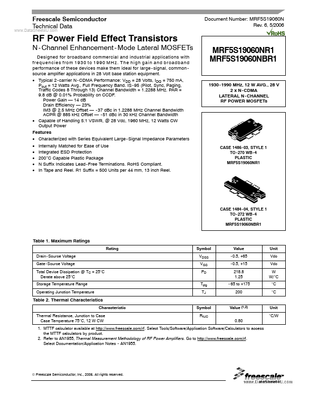
MRF5S19060NR1 MRF5S19060NBR1
- 1990 MHz, 12 W AVG., 28 V 2 x N
- CDMA LATERAL N
- CHANNEL RF POWER MOSFETs
CASE...