GFD 4N60F
This Power MOSFET is produced using advanced planar stripe DMOS technology. This latest technology has been especially designed to minimize on-state resistance, Have a high rugged avalanche characteristics.These devices are well suited for high efficiency switched mode power supplies, active power factor correction.electronic lamp ballasts based on half bridge topology.| Part No. | 4N60F |
|---|---|
| Datasheet | 4N60F Download |
| Manufacturer | GFD |
| Description | 600V N-Channel MOSFET |
| Buy | Stock & Price |
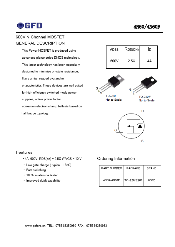
GENERAL DESCRIPTION
4N60/4N60F VDSS RDS(ON) ID 600V 2.5Ω 4AFEATURES
● 4A, 600V, RDS(on) = 2.5Ω @VGS = 10 V● Low gate charge ( typical 16nC)
● Fast switching
● 100% avalanche tested
● Improved dv/dt capability Ordering Information PART NUMBER PACKAGE BRAND 4N60/4N60F TO-220/220F 0GFD TEL:0755-86350980 FAX:0755-86350963 4N60/4N60F
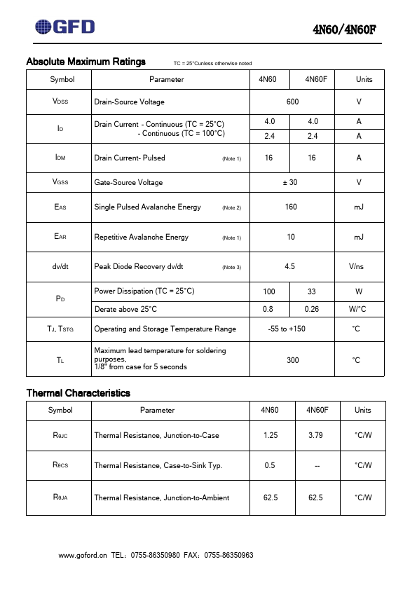
ABSOLUTE MAXIMUM RATINGS
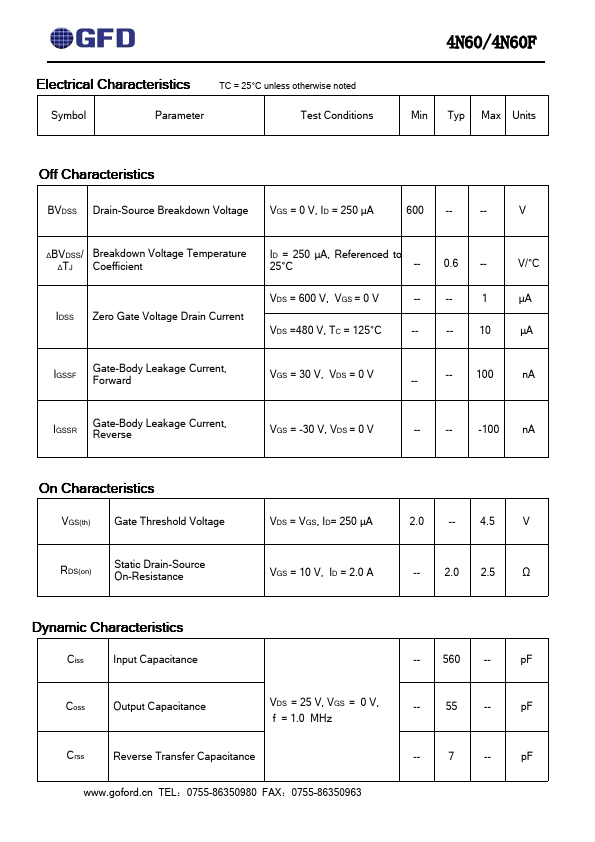
TC = 25°Cunless otherwise noted Symbol Parameter 4N60 4N60F VDSS ID Drain-Source Voltage Drain Current - Continuous (TC = 25°C) - Continuous (TC = 100°C) 600 4.0 4.0 2.4 2.4 IDM Drain Current- Pulsed (Note 1) 16 16 VGSS Gate-Source Voltage ± 30 EAS Single Pulsed Avalanche Energy (Note 2) 160 Units V A A A V mJ EAR Repetitive Avalanche Energy (Note 1) 10 mJ dv/dt Peak Diode Recovery dv/dt (Note 3) 4.5 V/ns PD TJ, TSTG TL Power Dissipation (TC = 25°C) Derate above 25°C Operating and Storage Temperature Range Maximum lead temperature for soldering purposes, 1/8" from case for 5 seconds 100 33 0.8 0.26 -55 to +150 300 W W/°C °C °C Thermal Characteristics Symbol Parameter 4N60 4N60F Units RθJC Thermal Resistance, Junction-to-Case 1.25 3.79 °C/W RθCS Thermal Resistance, Case-to-Sink Typ.