Datasheet4U Logo Datasheet4U.com

IXFH140N10P - N-Channel Power MOSFET

Download the IXFH140N10P datasheet PDF. This datasheet also covers the IXFT140N10P variant, as both devices belong to the same n-channel power mosfet family and are provided as variant models within a single manufacturer datasheet.

Key Features

  • l International standard packages l Unclamped Inductive Switching (UIS) rated l Low package inductance - easy to drive and to protect Symbol Test Conditions (T J = 25° C, unless otherwise specified) BVDSS VGS = 0 V, ID = 250 µA VGS(th) VDS = VGS, ID = 4.0 mA I GSS V GS = ±20 V, DC V DS = 0 IDSS VDS = VDSS VGS = 0 V RDS(on) VGS = 10 V, ID = 0.5 ID25 VGS = 15 V, ID = 300 A Note 1 Characteristic Values Min. Typ. Max. 100 V 3.0 5.0 V Advantages l Easy to mount l Space.

📥 Download Datasheet

Note: The manufacturer provides a single datasheet file (IXFT140N10P_IXYSCorporation.pdf) that lists specifications for multiple related part numbers.

Full PDF Text Transcription (Reference)

The following content is an automatically extracted verbatim text from the original manufacturer datasheet and is provided for reference purposes only.

View original datasheet text
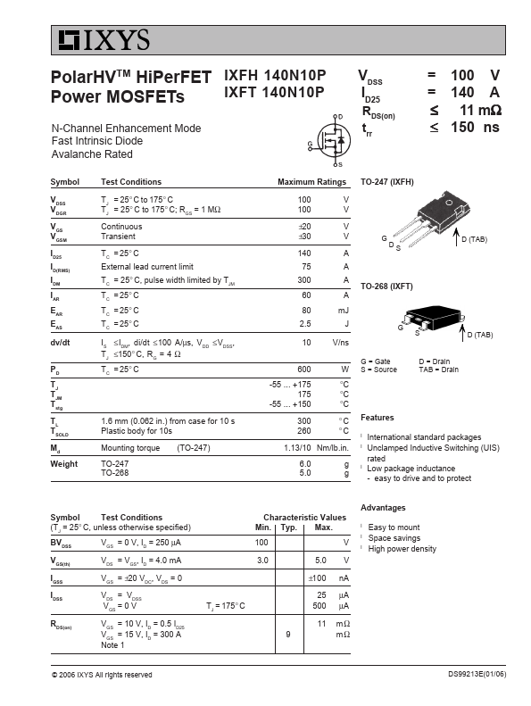
PolarHVTM HiPerFET IXFH 140N10P Power MOSFETs IXFT 140N10P N-Channel Enhancement Mode Fast Intrinsic Diode Avalanche Rated V DSS ID25 RDS(on) trr = 100 V = 140 A ≤ 11 mΩ ≤ 150 ns Symbol V DSS VDGR VGS VGSM ID25 ID(RMS) IDM IAR E AR EAS dv/dt PD TJ T JM Tstg TL TSOLD M d Weight Test Conditions T J = 25° C to 175° C TJ = 25° C to 175° C; RGS = 1 MΩ Continuous Transient TC = 25° C External lead current limit TC = 25° C, pulse width limited by TJM TC = 25° C T C = 25° C TC = 25° C I S ≤ I, DM di/dt ≤ 100 A/µs, V DD ≤ V, DSS T J ≤150° C, R G = 4 Ω TC = 25° C 1.6 mm (0.062 in.