IXFH80N085 Description
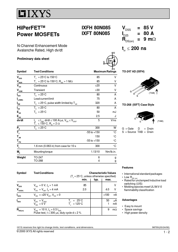
HiPerFETTM Power MOSFETs N-Channel Enhancement Mode Avalanche Rated, High dv/dt Preliminary data sheet IXFH 80N085 IXFT 80N085 VDSS = 85 V = 80 A ID25 RDS(on) = 9 mW trr £ 200 ns Symbol VDSS VDGR VGS VGSM ID25 IL(RMS) IDM IAR EAR EAS dv/dt PD TJ TJM Tstg TL.
IXFH80N085 Key Features
- Easy to mount
- Space savings
- High power density
- International standard packages
- Low RDS (on)
- Rated for unclamped Inductive load switching (UIS)
- Molding epoxies meet UL 94 V-0 flammability classification
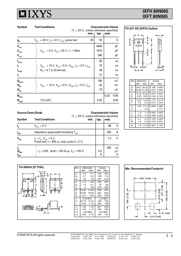
- VDSS, ID = 0.5
- VDSS, ID = 0.5
- ID25 42 75 0.42 (TO-247) 0.25 S pF pF pF ns ns ns ns nC nC nC K/W K/W