Datasheet4U Logo Datasheet4U.com

2ED21064S06J - 650V high-side and low-side gate driver

Download the 2ED21064S06J datasheet PDF. This datasheet also covers the 2ED2106S06F variant, as both devices belong to the same 650v high-side and low-side gate driver family and are provided as variant models within a single manufacturer datasheet.

General Description

The 2ED2106(4)S06F(J) is a high voltage, high speed power MOSFET and IGBT driver with independent high and low side referenced output channels.

Key Features

  • Product summary.
  • Unique Infineon Thin-Film-Silicon On Insulator (SOI)-technology.
  • Negative VS transient immunity of 100 V.
  • Floating channel designed for bootstrap operation.
  • Operating voltages (VS node) upto + 650 V.
  • Maximum bootstrap voltage (VB node) of + 675 V.
  • Integrated ultra-fast, low resistance bootstrap diode.
  • Logic operational up to.
  • 11 V on VS Pin.
  • Negative voltage tolerance on inputs of.
  • 5 V.
  • Independent under voltage lock.

📥 Download Datasheet

Note: The manufacturer provides a single datasheet file (2ED2106S06F-Infineon.pdf) that lists specifications for multiple related part numbers.

Datasheet Details

Part number 2ED21064S06J
Manufacturer Infineon
File Size 1.09 MB
Description 650V high-side and low-side gate driver
Datasheet download datasheet 2ED21064S06J Datasheet

Full PDF Text Transcription (Reference)

The following content is an automatically extracted verbatim text from the original manufacturer datasheet and is provided for reference purposes only.

View original datasheet text
2ED2106 (4) S06F (J) 2ED2106 (4) S06F (J) 
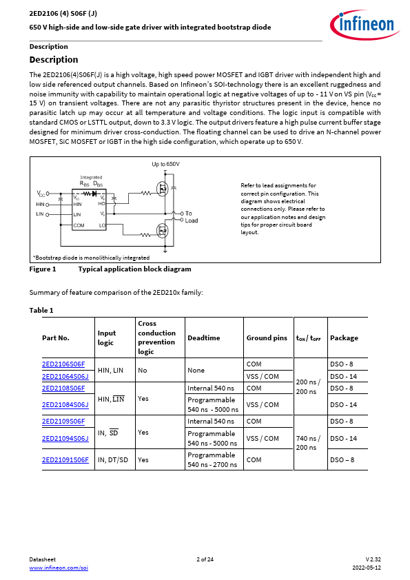
650 V high-side and low-side gate driver with integrated bootstrap diode Features Product summary  Unique Infineon Thin-Film-Silicon On Insulator (SOI)-technology  Negative VS transient immunity of 100 V  Floating channel designed for bootstrap operation  Operating voltages (VS node) upto + 650 V  Maximum bootstrap voltage (VB node) of + 675 V  Integrated ultra-fast, low resistance bootstrap diode  Logic operational up to –11 V on VS Pin  Negative voltage tolerance on inputs of –5 V  Independent under voltage lockout for both channels  Schmitt trigger inputs with hysteresis  3.