IRF614SPBF Overview
Key Specifications
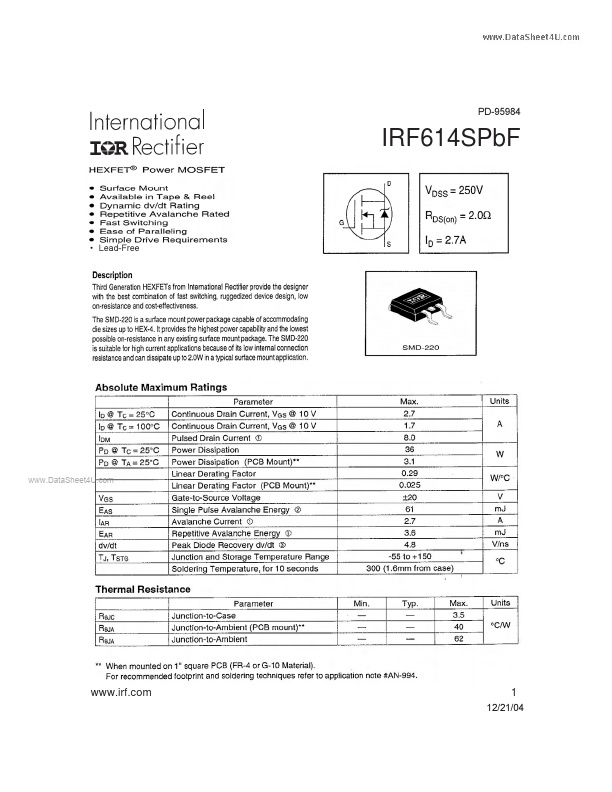
Package: D2PAK
Mount Type: Surface Mount
Pins: 3
Height: 4.83 mm
Key Features
- Low Stray Inductance
- Ground Plane
| Part | IRF614SPBF |
|---|---|
| Description | HEXFET Power MOSFET |
| Category | MOSFET |
| Manufacturer | International Rectifier |
| Size | 1.71 MB |
Package: D2PAK
Mount Type: Surface Mount
Pins: 3
Height: 4.83 mm
| Seller | Inventory | Price Breaks | Buy |
|---|---|---|---|
| TME | 0 | 1+ : 1.14 USD 10+ : 1.03 USD 50+ : 0.91 USD 250+ : 0.81 USD |
View Offer |
| TME | 0 | 1+ : 1.14 EUR 10+ : 1.03 EUR 50+ : 0.91 EUR 250+ : 0.81 EUR |
View Offer |
| Part Number | Manufacturer | Description |
|---|---|---|
| IRF614S | Fairchild Semiconductor | Power MOSFET |
| IRF614S | Vishay | Power MOSFET |
| IRF614 | Inchange Semiconductor | N-Channel Mosfet Transistor |
| IRF614 | Intersil | N-Channel Power MOSFET |
| IRF614B | Fairchild Semiconductor | 250V N-Channel MOSFET |