IRF6603
IRF6603 is HEXFETPower MOSFET manufactured by International Rectifier.
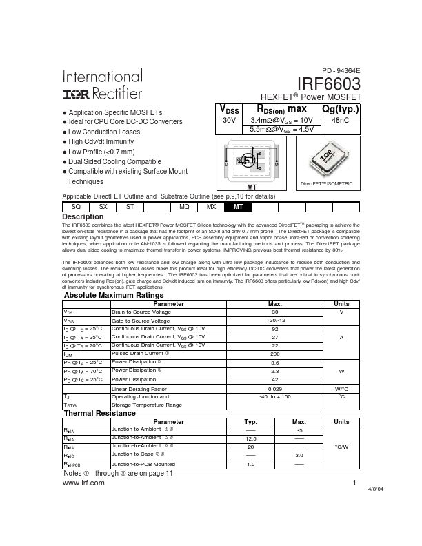
Description
The IRF6603 bines the latest HEXFET® Power MOSFET Silicon technology with the advanced Direct FETTM packaging to achieve the lowest on-state resistance in a package that has the footprint of an SO-8 and only 0.7 mm profile. The Direct FET package is patible with existing layout geometries used in power applications, PCB assembly equipment and vapor phase, infra-red or convection soldering techniques, when application note AN-1035 is followed regarding the manufacturing methods and process. The Direct FET package allows dual sided cooling to maximize thermal transfer in power systems, IMPROVING previous best thermal resistance by 80%. The IRF6603 balances both low resistance and low charge along with ultra low package inductance to reduce both conduction and switching losses. The reduced total losses make this product ideal for high efficiency DC-DC converters that power the latest generation of processors operating at higher frequencies. The IRF6603 has been optimized for parameters that are critical in synchronous buck converters including Rds(on), gate charge and Cdv/dt-induced turn on immunity. The IRF6603 offers particularly low Rds(on) and high Cdv/ dt immunity for synchronous FET applications.
Absolute Maximum Ratings
Parameter
VDS VGS ID @ TC = 25°C ID @ TA = 25°C ID @ TA = 70°C IDM PD @TA = 25°C PD @TA = 70°C PD @TC = 25°C TJ TSTG Drain-to-Source Voltage Gate-to-Source Voltage Continuous Drain Current, VGS @ 10V Continuous Drain Current, VGS @ 10V Continuous Drain Current, VGS @ 10V Pulsed Drain Current
Max.
30 +20/-12 92 27 22 200 3.6 2.3 42 0.029 -40 to + 150
Units
A g Power Dissipation g
Power Dissipation Power Dissipation c
W W/°C °C
Linear Derating Factor Operating Junction and Storage Temperature Range
Thermal Resistance
RθJA RθJA RθJA RθJC RθJ-PCB fj Junction-to-Ambient gj Junction-to-Ambient hj Junction-to-Case ij
Junction-to-Ambient
Parameter
Typ.
- -
- 12.5 20
- -
- 1.0
Max.
- -
- -
- - 3.0
- -
- Units
°C/W
Junction-to-PCB...