IRF6613
Description
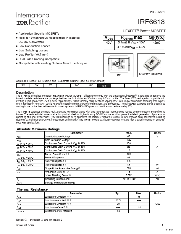
The IRF6613 bines the latest HEXFET® Power MOSFET Silicon technology with the advanced Direct FETTM packaging to achieve the lowest on-state resistance in a package that has the footprint of an SO-8 and only 0.7 mm profile. The Direct FET package is patible with existing layout geometries used in power applications, PCB assembly equipment and vapor phase, infra-red or convection soldering techniques, when application note AN-1035 is followed regarding the manufacturing methods and processes. The Direct FET package allows dual sided cooling to maximize thermal transfer in power systems, IMPROVING previous best thermal resistance by 80%. The IRF6613 balances both low resistance and low charge along with ultra low package inductance to reduce both conduction and switching losses. The reduced total losses make this product ideal for high efficiency DC-DC converters that power the latest generation of processors operating at higher frequencies. The IRF6613 has been optimized for...