LS7290
LS7290 is STEPPER MOTOR CONTROLLER manufactured by LSI.
FEATURES
:
- -
- -
- -
- -
- -
- -
- July 2011
Controls Bipolar and Unipolar motors Cost-effective replacement for L297 Full, ½ step mode selected with mode input Direction control Reset input Step control input Enable input PWM chopper circuit for current control Two peak-current parators with external reference input Step control frequency and duty cycle controlled by an external frequency source or by an internal crystal controlled oscillator (typically 8 MHz) All inputs and outputs TTL/CMOS patible (TTL for 5V operation) 3V to 5.5V Operation (VDD
- VSS) LS7290 (DIP), LS7290-S (SOIC), LS7290-TS (TSSOP)
- See Figure 1.
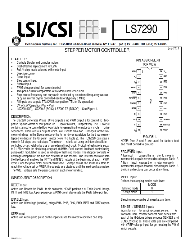
PIN ASSIGNMENT TOP VIEW
DESCRIPTION
:
The LS7290 generates Phase Drive outputs a nd PWM output s for controlling twophase Bipolar Motors or four-phase Un ipolar Motors, respectively. The LS7290 contains a mod e controlled loo k-up table for generating the motor duty cycle drive sequences. There are four outputs which are used to drive two H-Bridges for the two motor windings in the Bipolar motor or the fo ur driver transistors for the t wo ce ntertapped windings in the Unipolar motor (Refe r t o Table 2). The LS7290 can st ep a motor in full steps and half steps. The refresh rate is set using an internal oscillato r controlled by a crystal or by use of an external input clock. Typical refresh rate is equal to 31.25k Hz with the clock frequency set at 8MHz. Peak-current feedback control using pulse-width modulation is used in full-step or half-step modes. The chopper consists of a voltage parator, flip-flop and external se nse resistor. The internal oscillator sets the flip-flop and enables the INH1 and INH2 o utputs at the beginning of each PWM cycle. Once the peak motor current causes the voltage across t he sense resi stors to reach the voltage set by VREF, the outputs ar e disabled until the next oscillator pulse. The VREF voltage sets the peak current in each motor winding.
FIGURE 1.
NOTE: Pins 2 and 3 are used for factory test and must be...