STY25NA60
STY25NA60 is N-CHANNEL Power MOSFET manufactured by STMicroelectronics.
®
- CHANNEL 600V
- 0.225Ω
- 25 A
- Max247 EXSTREMELY LOW GATE CHARGE POWER MOSFET
TYPE STY25NA60 s s
V DSS 600 V
R DS(on) < 0.24 Ω
ID 25 A s s s s s
TYPICAL RDS(on) = 0.225 Ω EFFICIENT AND RELIABLE MOUNTING THROUGH CLIP ± 30V GATE TO SOURCE VOLTAGE RATING 100% AVALANCHE TESTED LOW INTRINSIC CAPACITANCE GATE CHARGE MINIMIZED REDUCED VOLTAGE SPREAD
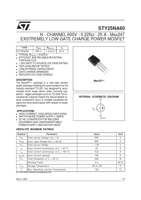
DESCRIPTION The Max247™ package is a new high volume power package exibiting the same footprint as the industry standard TO-247, but designed to acodate much larger silicon chips, normally supplied in bigger packages such as TO-264.The increased die capacity makes the device idealto reduce ponent count in multiple paralleled designs and save board space with respect to larger packages. APPLICATIONS HIGH CURRENT, HIGH SPEED SWITCHING s SWITCH MODE POWER SUPPLY (SMPS) s DC-AC CONVERTER FOR WELDING EQUIPMENT AND UNINTERRUPTABLE POWER SUPPLY AND MOTOR DRIVE s
Max247™
INTERNAL SCHEMATIC...