Datasheet Summary
Ordering number :EN5848
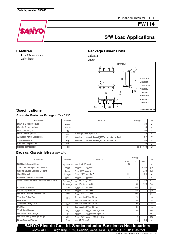
P-Channel Silicon MOS FET
S/W Load Applications
Features
- Low ON resistance.
- 2.5V drive.
Package Dimensions unit:mm 2129
[FW114] 85
0.1 1.5 1.8max 4.4 0.3 6.0
1 5.0
Specifications...
| Part Number | Description |
|---|---|
| FW111 | P-Channel Silicon MOSFET |
| FW113 | P-Channel Silicon MOS FET |
| FW115 | P-Channel Silicon MOS FET |
| FW103 | P-Channel Silicon MOSFET |
| FW133 | P-Channel Silicon MOSFET |