BFY280
BFY280 is HiRel NPN Silicon RF Transistor (HiRel Discrete and Microwave Semiconductor) manufactured by Siemens Semiconductor Group.
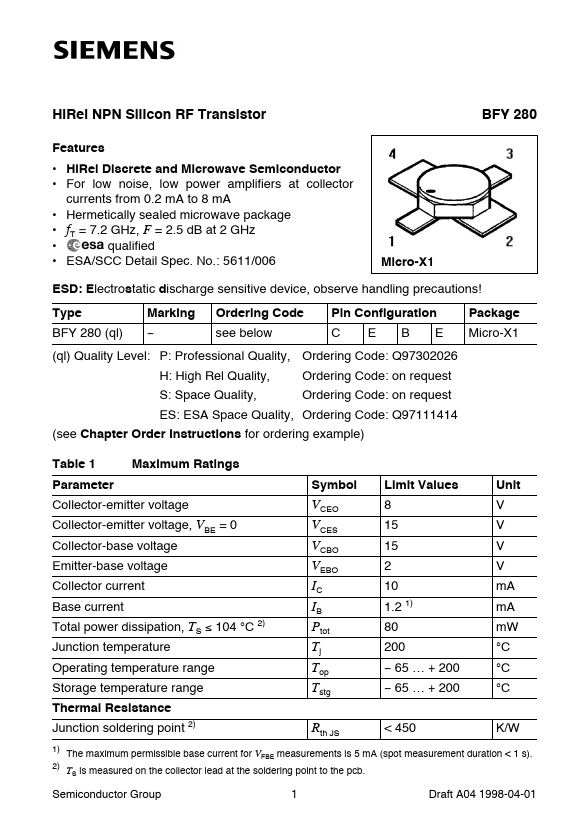
Hi Rel NPN Silicon RF Transistor
Features
- Hi Rel Discrete and Microwave Semiconductor
- For low noise, low power amplifiers at collector currents from 0.2 m A to 8 m A
- Hermetically sealed microwave package
- f T = 7.2 GHz, F = 2.5 d B at 2 GHz
- qualified
- ESA/SCC Detail Spec. No.: 5611/006
BFY 280
Micro-X1
ESD: Electrostatic discharge sensitive device, observe handling precautions! Type BFY 280 (ql) Marking Ordering Code see below H: High Rel Quality, S: Space Quality, Pin Configuration C E B E Package Micro-X1
(ql) Quality Level: P: Professional Quality, Ordering Code: Q97302026 Ordering Code: on request Ordering Code: on request
ES: ESA Space Quality, Ordering Code: Q97111414 (see Chapter Order Instructions for ordering example) Table 1 Parameter Collector-emitter voltage Collector-emitter voltage, VBE = 0 Collector-base voltage Emitter-base voltage Collector current Base current Total power dissipation, TS £ 104 °C 2) Junction temperature Operating temperature range Storage temperature range Thermal Resistance Junction soldering point 2)
1) 2)
Maximum Ratings Symbol Limit Values 8 15 15 2 10 1.2 1) 80 200
- 65 É + 200
- 65 É + 200 < 450 Unit V V V V m A m A m W °C °C °C K/W
VCEO VCES VCBO VEBO IC IB Ptot Tj Top Tstg Rth JS
The maximum permissible base current for VFBE measurements is 5 m A (spot measurement duration < 1 s).
TS is measured on the collector lead at the soldering point to the pcb.
Semiconductor Group
Draft A04 1998-04-01
BFY 280
Electrical Characteristics Table 2 Parameter Collector-base cutoff current VCB = 10 V, IE = 0 Collector-emitter cutoff current VCE = 8 V, IB = 0.1 m A 3) Collector-base cutoff current VCB = 8 V, IE = 0 Emitter-base cutoff current VEB = 2 V, IC = 0 Emitter-base cutoff current VEB = 1 V, IC = 0 Base-emitter forward voltage IE = 5 m A, IC = 0 DC current gain IC = 0.25 m A, VCE = 1 V
3)
DC Characteristics at TA = 25 °C unless otherwise specified Symbol min. Limit Values typ. 100 max. 100 100 50 25 0.5 1 175 m A m A n A m...