DESCRIPTION
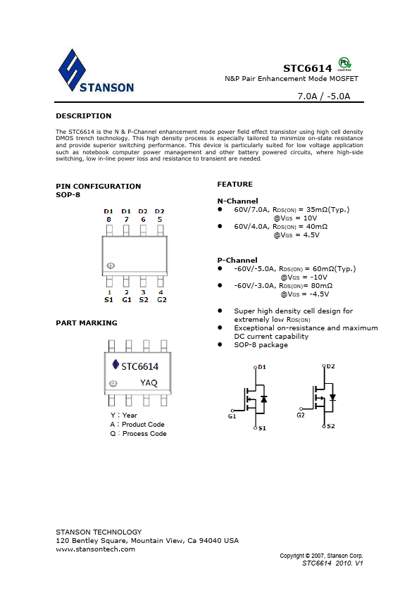
PIN CONFIGURATION SOP-8 FEATURE N-Channel 60V/7.0A, RDS(ON) = 35mΩ(Typ.) @VGS = 10V 60V/4.0A, RDS(ON) = 40mΩ @VGS = 4.5V PART MARKING P-Channel -60V/-5.0A, RDS(ON) = 60mΩ(Typ.) @VGS = -10V -60V/-3.0A, RDS(ON)= 80mΩ @VGS = -4.5V Super high density cell design for extremely low RDS(ON) Exceptional on-resistance and maximum DC current capability SOP-8 package Y∶Year A∶Product Code Q︰Process Code STANSON TECHNOLOGY 120 Bentley Square, Mountain View, Ca 94040 USA Copyright © 2007, Stanson Corp. STC6614 2010. V1 STC6614 N&P Pair Enhancement Mode MOSFET 7.0A / -5.0A ABSOULTE MAXIMUM RATINGS
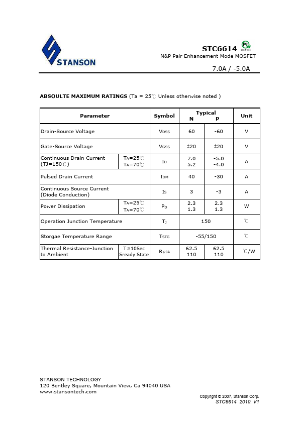
(Ta = 25℃ Unless otherwise noted ) Parameter Drain-Source Voltage Symbol VDSS Typical NP 60 -60 Gate-Source Voltage Continuous Drain Current (TJ=150℃) TA=25℃ TA=70℃ Pulsed Drain Current Continuous Source Current (Diode Conduction) Power Dissipation TA=25℃ TA=70℃ Operation Junction Temperature VGSS ID IDM IS PD TJ ±20 ±20 7.0 -5.0 5.2 -4.0 40 -30 3 -3 2.3 2.3 1.3 1.3 150 Storgae Temperature Rang... Stanson Technology