WILLAS FMMT495
This is the preliminary specification.| Part No. | FMMT495 |
|---|---|
| Datasheet | FMMT495 Download |
| Manufacturer |  WILLAS |
| Description | NPN Plastic-Encapsulate Transistors |
| Buy | Stock & Price |
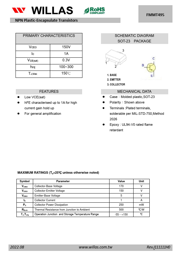
FEATURES
● Low VCE(sat)● hFE characterised up to 1A for high current gain hold up
● For general amplification FMMT495 SCHEMATIC DIAGRAM SOT-23 PACKAGE 3 1 2 1. BASE 2. EMITTER 3. COLLECTOR
MECHANICAL DATA
● Case:Molded plastic,SOT-23● Polarity:Shown above
● Terminals :Plated terminals, solderable per MIL-STD-750,Method 2026
● Epoxy : UL94-V0 rated flame retardant
MAXIMUM RATINGS
(Ta=25℃ unless otherwise noted) Symbol VCBO VCEO VEBO IC PC RΘJA TJ,Tstg Parameter Collector-Base Voltage Collector-Emitter Voltage Emitter-Base Voltage Collector Current Collector Power Dissipation Thermal Resistance from Junction to Ambient Operation Junction and Storage Temperature Range Value 170 150 5 1 250 500 -55~+150 Unit V V V A mW ℃/W ℃ 2022.08 Rev.J111111H0 NPN Plastic-Encapsulate Transistors FMMT495ELECTRICAL CHARACTERISTICS
(Ta=25℃ unless otherwise specified) Symbol Parameter V(BR)CBO V(BR)CEO * Collector-base breakdown voltage Collector-emitter breakdown voltage V(BR)EBO Emitter-base breakdown...