CDC318A
CDC318A is 1-Line To 18-Line Clock Driver manufactured by Texas Instruments.
description
The CDC318A is a high-performance clock buffer designed to distribute high-speed clocks in PC applications. This device distributes one input (A) to 18 outputs (Y) with minimum skew for clock distribution. The CDC318A operates from a 3.3-V power supply. It is characterized for operation from 0°C to 70°C.
This device has been designed with consideration for optimized EMI performance. Depending on the application layout, damping resistors in series to the clock outputs (like proposed in the PC100 specification) may not be needed in most cases.
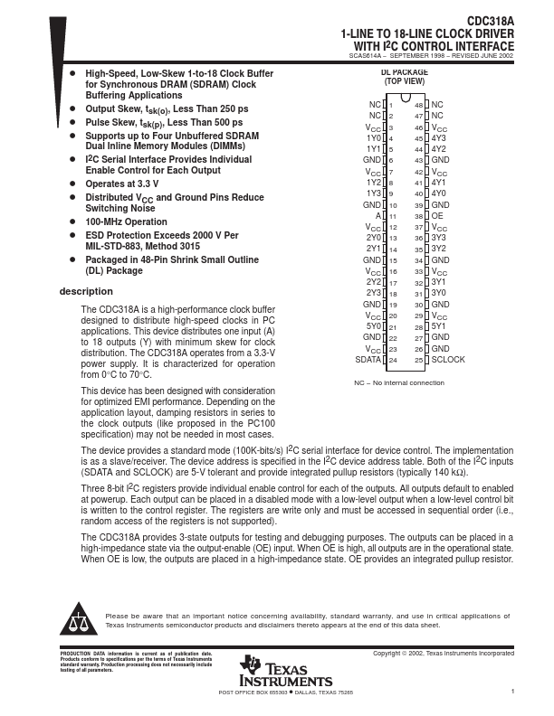
DL PACKAGE (TOP VIEW)
NC 1 NC 2 VCC 3 1Y0 4 1Y1 5 GND 6 VCC 7 1Y2 8 1Y3 9 GND 10
A 11 VCC 12 2Y0 13 2Y1 14 GND 15 VCC 16 2Y2 17 2Y3 18 GND 19 VCC 20 5Y0 21 GND 22 VCC 23 SDATA 24
48 NC 47 NC 46 VCC 45 4Y3 44 4Y2 43 GND 42 VCC 41 4Y1 40 4Y0 39 GND 38 OE 37 VCC 36 3Y3 35 3Y2 34 GND 33 VCC 32 3Y1 31 3Y0 30 GND 29 VCC 28 5Y1 27 GND 26 GND 25 SCLOCK
- No internal connection
The device provides a standard mode (100K-bits/s) I2C serial interface for device control. The implementation is as a slave/receiver. The device address is specified in the I2C device address table. Both of the I2C inputs
(SDATA and SCLOCK) are 5-V tolerant and provide integrated pullup resistors (typically 140 kΩ).
Three 8-bit I2C registers provide individual enable control for each of the outputs. All outputs default to enabled at powerup. Each output can be placed in a disabled mode with a low-level output when a low-level control bit is written to the control register. The registers are write only and must be accessed in sequential order (i.e., random access of the registers is not supported).
The CDC318A provides 3-state outputs for testing and debugging purposes. The outputs can be placed in a high-impedance state via the output-enable (OE) input. When OE is high, all outputs are in the operational state. When OE is low, the outputs are placed in a high-impedance state. OE provides an integrated pullup resistor.
Please be aware that...