SN74ACT1073DW Overview
Key Specifications
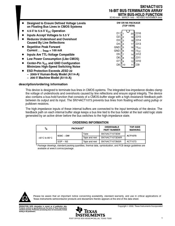
Package: SOIC
Mount Type: Surface Mount
Pins: 20
Operating Voltage: 5.5 V
Key Features
- 2000-V Human-Body Model (A114-A)
- 200-V Machine Model (A115-A)
| Part | SN74ACT1073DW |
|---|---|
| Description | 16-BIT BUS-TERMINATION ARRAY |
| Manufacturer | Texas Instruments |
| Size | 1.02 MB |
Package: SOIC
Mount Type: Surface Mount
Pins: 20
Operating Voltage: 5.5 V
| Seller | Inventory | Price Breaks | Buy |
|---|---|---|---|
| Rochester Electronics | 25681 | 25+ : 2.08 USD 100+ : 1.98 USD 500+ : 1.87 USD 1000+ : 1.77 USD |
View Offer |
| Verical | 9681 | 152+ : 2.475 USD 500+ : 2.3375 USD 1000+ : 2.2125 USD 10000+ : 2.075 USD |
View Offer |
| Part Number | Manufacturer | Description |
|---|---|---|
| CTA2P1N | Diodes Incorporated | COMPLEX TRANSISTOR ARRAY |
| CTA2N1P | Diodes Incorporated | COMPLEX TRANSISTOR ARRAY |
| 7003 | Allegro MicroSystems | HIGH-VOLTAGE/ HIGH-CURRENT DARLINGTON ARRAY |