IR3313PBF
Description
The IR3313PbF is a fully protected 4 terminals high side switch. The input signal is referenced to Vcc.
Key Features
- 6 to 32V Current Ratio 8800 Prog
- Ishutdown 10 to 90A Vclamp 40V Packages
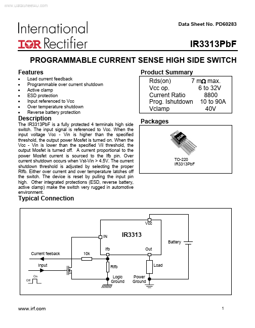
The IR3313PbF is a fully protected 4 terminals high side switch. The input signal is referenced to Vcc.