MTB6N60E Overview
Key Features
- Channel Enhancement
- Mode Silicon Gate
| Part | MTB6N60E |
|---|---|
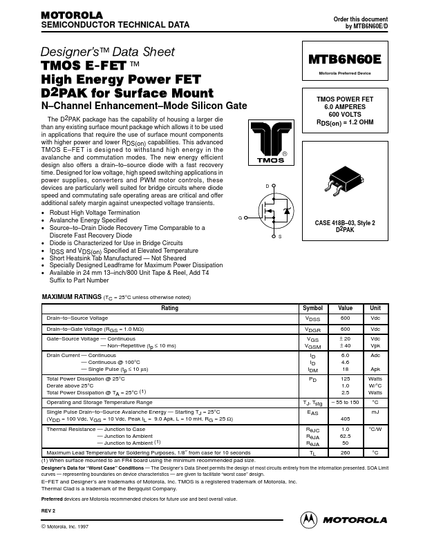
| Description | TMOS POWER FET |
| Manufacturer | Motorola Semiconductor |
| Size | 192.40 KB |
| Part Number | Manufacturer | Description |
|---|---|---|
| MTB6N60E1 | onsemi | High Energy Power FET |