Datasheet Details
| Part number | 74LVC2G04 |
|---|---|
| Manufacturer | DIODES |
| File Size | 461.63 KB |
| Description | DUAL INVERTERS |
| Datasheet |
 74LVC2G04 Datasheet 74LVC2G04 Datasheet
|
|
|
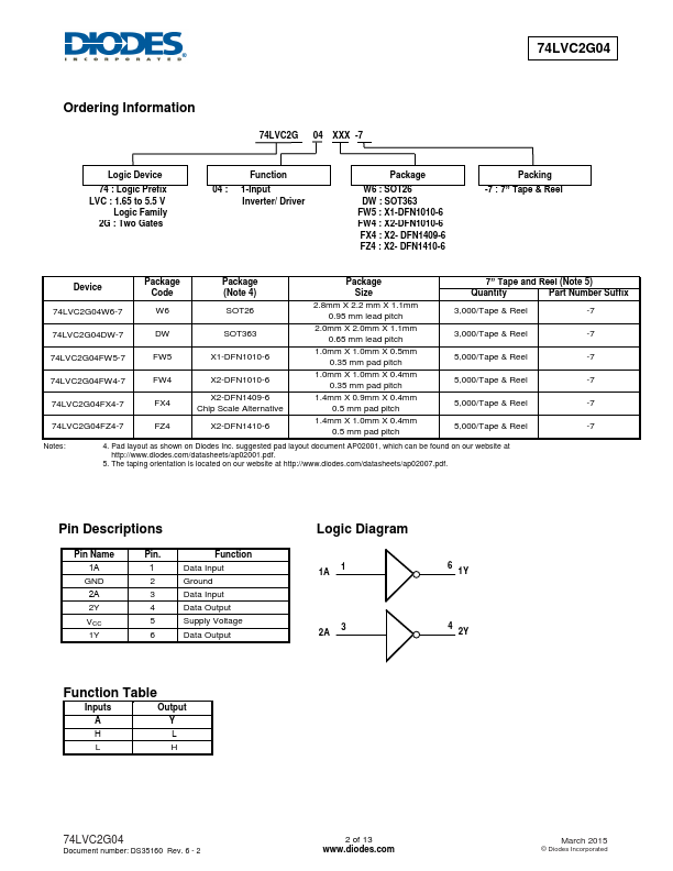
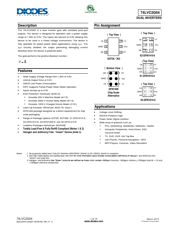
The 74LVC2G04 is a dual inverter gate with standard push-pull outputs.
The device is designed for operation with a power supply range of 1.65V to 5.5V.
The inputs are tolerant to 5.5V allowing this device to be used in a mixed voltage environment.
| Part number | 74LVC2G04 |
|---|---|
| Manufacturer | DIODES |
| File Size | 461.63 KB |
| Description | DUAL INVERTERS |
| Datasheet |
74LVC2G04 Datasheet
|
|
|
|