Datasheet Details
| Part number | HIP5011 |
|---|---|
| Manufacturer | Intersil Corporation |
| File Size | 38.37 KB |
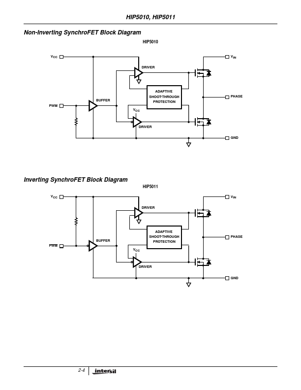
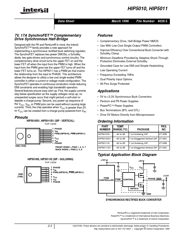
| Description | 7V/ 17A SynchroFET Complementary Drive Synchronous Half-Bridge |
| Datasheet |
 HIP5011_IntersilCorporation.pdf HIP5011_IntersilCorporation.pdf
|
|
|
The HIP5011 by Intersil Corporation is a 7V/ 17A SynchroFET Complementary Drive Synchronous Half-Bridge. Below is the official datasheet preview.
| Part number | HIP5011 |
|---|---|
| Manufacturer | Intersil Corporation |
| File Size | 38.37 KB |
| Description | 7V/ 17A SynchroFET Complementary Drive Synchronous Half-Bridge |
| Datasheet |
HIP5011_IntersilCorporation.pdf
|
|
|
|
SYMBOL VCC VIN PHASE PWM (HIP5010) PWM (HIP5011) GND DESCRIPTION Positive supply to control logic and gate drivers.
📁 HIP5011 Similar Datasheet