IXFC36N50P
IXFC36N50P is Polar MOSFETs manufactured by IXYS.
Advance Technical Information
Polar HVTM Hi Per FET Power MOSFET
..
IXFC 36N50P IXFR 36N50P
VDSS ID25
(Electrically Isolated Back Surface)
N-Channel Enhancement Mode Avalanche Rated Fast Intrinsic Diode
= = RDS(on) ≤ ≤ trr
500 18 190 250
V A mΩ ns
Symbol VDSS VDGR VGSS VGSM ID25 IDM IAR EAR EAS dv/dt PD TJ TJM Tstg TL VISOL FC Weight
Test Conditions TJ = 25°C to 150°C TJ = 25°C to 150°C; RGS = 1 MΩ Continuous Transient TC = 25°C TC = 25°C, pulse width limited by TJM TC = 25°C TC = 25°C TC = 25°C IS ≤ IDM, di/dt ≤ 100 A/μs, VDD ≤ VDSS, TJ ≤ 150°C, RG = 4 Ω TC = 25°C
Maximum Ratings 500 500 ± 30 ± 40 18 100 24 50 1.5 20 156 -55 ... +150 150 -55 ... +150 V V V V A A A m J J V/ns
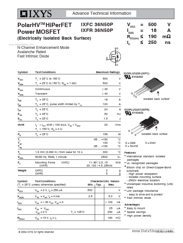
ISOPLUS220 (IXFC) E153432
Isolated back surface-
ISOPLUS247 (IXFR) E153432
W °C °C °C °C V~ N/lb g g
Isolated back surface
D = Drain
G = Gate S = Source
1.6 mm (0.062 in.) from case for 10 s 50/60 Hz, RMS, 1 minute Mounting Force (IXFR) (IXFC) (IXFR) (IXFC)
300 2500 11..65 / 2.5..15 20..120 / 4.5..25N/lb 3 5
Features z International standard isolated packages z UL recognized packages z
Symbol Test Conditions (TJ = 25°C unless otherwise specified) VDSS VGS(th) IGSS IDSS RDS(on) VGS = 0 V, ID = 250 μA VDS = VGS, ID = 4 m A VGS = ± 30 VDC, VDS = 0 VDS = VDSS VGS = 0 V VGS = 10 V, ID = IT TJ = 125°C
Characteristic Values Min. Typ. Max. 500 2.5 5.0 ± 100 25 250 190 V V n A μA μA mΩ z z z
Silicon chip on Direct-Copper-Bond substrate
- High power dissipation
- Isolated mounting surface
- 2500V electrical isolation Unclamped Inductive Switching (UIS) rated Low package inductance
- easy to drive and to protect Fast intrinsic...