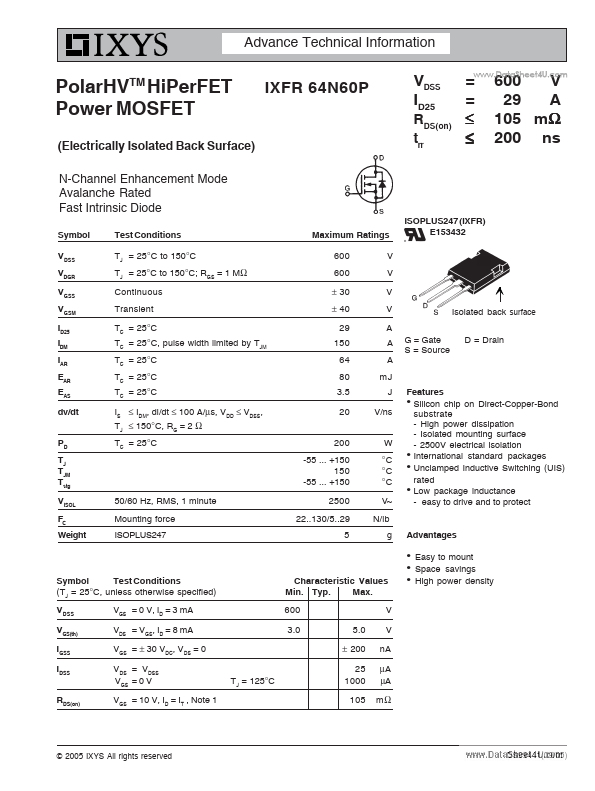
z Silicon chip on Direct-Copper-Bond substrate - High power dissipation - Isolated mounting surface - 2500V electrical isolation z International standard packages z Unclamped Inductive Switching (UIS) rated z Low package inductance - easy to drive and to protect Advantages
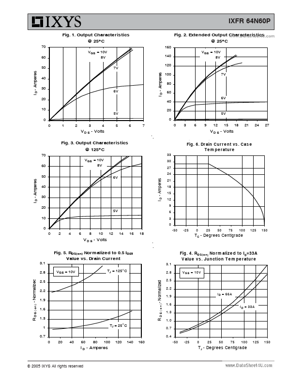
z z
Symbol Test Conditions (TJ = 25°C, unless otherwise specified) VDSS VGS(th) IGSS IDSS RDS(on) VGS = 0 V, ID = 3 mA VDS = VGS, ID = 8 mA VGS = ± 30 VDC, VDS = 0 VDS = VDSS VGS = 0 V VGS = 10 V, ID = IT , Note 1 TJ = 125°C.
Full PDF Text Transcription for IXFR64N60P (Reference)
Note: Below is a high-fidelity text extraction (approx. 800 characters) for
IXFR64N60P. For precise diagrams, and layout, please refer to the original PDF.
Advance Technical Information PolarHV HiPerFET Power MOSFET TM IXFR 64N60P VDSS ID25 (Electrically Isolated Back Surface) N-Channel Enhancement Mode Avalanche Rated Fast ...
View more extracted text
solated Back Surface) N-Channel Enhancement Mode Avalanche Rated Fast Intrinsic Diode Symbol VDSS VDGR VGSS VGSM ID25 IDM IAR EAR EAS dv/dt PD TJ TJM Tstg VISOL FC Weight 50/60 Hz, RMS, 1 minute Mounting force ISOPLUS247 Test Conditions TJ = 25°C to 150°C TJ = 25°C to 150°C; RGS = 1 MΩ Continuous Transient TC = 25°C TC = 25°C, pulse width limited by TJM TC = 25°C TC = 25°C TC = 25°C IS ≤ IDM, di/dt ≤ 100 A/μs, VDD ≤ VDSS, TJ ≤ 150°C, RG = 2 Ω TC = 25°C Maximum Ratings 600 600 ± 30 ± 40 29 150 64 80 3.5 20 200 -55 ... +150 150 -55 ... +150 2500 22..130/5..29 5 V V V V A A A mJ J V/ns W °C °C °C V~ N/lb g RDS(on) trr = = ≤ ≤