IXFR66N50Q2 Description
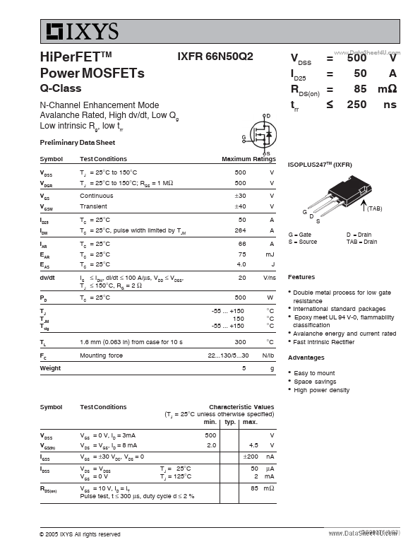
+150 300 22...130/5...30 5 V V V V A A A mJ J V/ns W °C °C °C °C N/lb g VDSS ID25 RDS(on) trr = = = ≤ .. 500 V 50 A 85 mΩ 250 ns ISOPLUS247TM (IXFR) G (TAB) D S D = Drain TAB = Drain G = Gate S = Source.
IXFR66N50Q2 Key Features
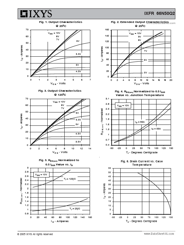
- Amperes
- Amperes