BFP181R Overview
Key Specifications
Max Operating Temp: 150 °C
Key Features
- soldering point 2) RthJS
| Part | BFP181R |
|---|---|
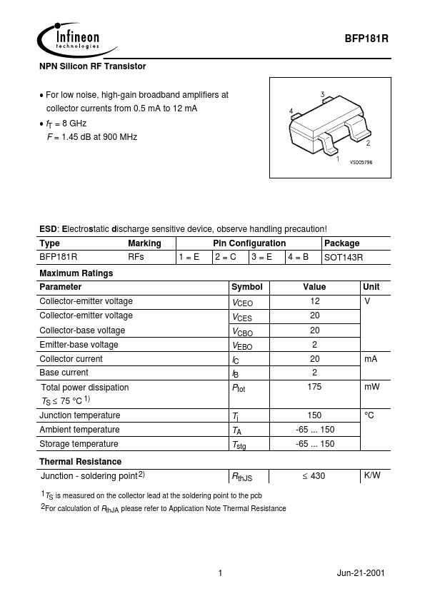
| Description | NPN Silicon RF Transistor |
| Category | Transistor |
| Manufacturer | Infineon |
| Size | 88.12 KB |
Max Operating Temp: 150 °C
| Seller | Inventory | Price Breaks | Buy |
|---|---|---|---|
| Win Source | 5 | - | View Offer |
| Part Number | Manufacturer | Description |
|---|---|---|
| BFP181R | Siemens Semiconductor Group | NPN Silicon RF Transistor |
| BFP181 | Siemens Semiconductor Group | NPN Silicon RF Transistor |
| BFP181TRW | Vishay | Silicon NPN Planar RF Transistor |
| BFP181T | Vishay | Silicon NPN Planar RF Transistor |
| BFP181TW | Vishay | Silicon NPN Planar RF Transistor |