BFP182 Overview
Key Specifications
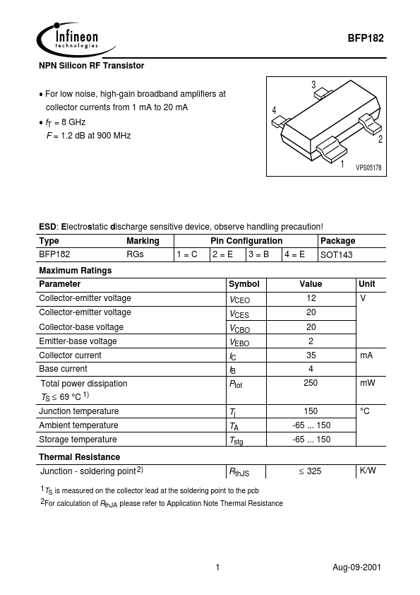
Package: SOT
Mount Type: Surface Mount
Pins: 4
Max Operating Temp: 150 °C
Key Features
- soldering point 2) RthJS
| Part | BFP182 |
|---|---|
| Description | NPN Silicon RF Transistor |
| Category | Transistor |
| Manufacturer | Infineon |
| Size | 78.93 KB |
Package: SOT
Mount Type: Surface Mount
Pins: 4
Max Operating Temp: 150 °C
| Seller | Inventory | Price Breaks | Buy |
|---|---|---|---|
| Rochester Electronics | 267831 | 100+ : 0.1434 USD 500+ : 0.1291 USD 1000+ : 0.119 USD 10000+ : 0.1061 USD |
View Offer |
| DigiKey | 0 | 9000+ : 0.11859 USD | View Offer |
| Part Number | Manufacturer | Description |
|---|---|---|
| BFP182T | Vishay | Silicon NPN Planar RF Transistor |
| BFP182TRW | Vishay | Silicon NPN Planar RF Transistor |
| BFP182TW | Vishay | Silicon NPN Planar RF Transistor |
| BFP182W | Siemens Semiconductor Group | NPN Silicon RF Transistor |
| BFP182 | Siemens Semiconductor Group | NPN Silicon RF Transistor |