BFR92T Overview
Key Specifications
Max Operating Temp: 150 °C
Key Features
- soldering point 2) RthJS
| Part | BFR92T |
|---|---|
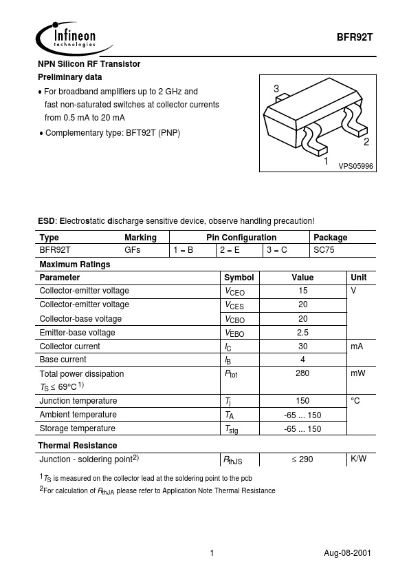
| Description | NPN Silicon RF Transistor |
| Category | Transistor |
| Manufacturer | Infineon |
| Size | 70.04 KB |
Max Operating Temp: 150 °C
| Seller | Inventory | Price Breaks | Buy |
|---|---|---|---|
| Win Source | 19500 | 6+ : 10.8293 USD 13+ : 8.8854 USD 21+ : 8.6082 USD 28+ : 8.3299 USD |
View Offer |
| Run Hong Electronics | 6768 | 1+ : 6.2892 USD | View Offer |
| Part Number | Manufacturer | Description |
|---|---|---|
| BFR92A | NXP Semiconductors | NPN 5GHz wideband transistor |
| BFR92 | NXP Semiconductors | NPN 5 GHz wideband transistor |
| BFR92A | Vishay | Silicon NPN Planar RF Transistor |
| BFR92AT | NXP Semiconductors | NPN 5 GHz wideband transistor |
| BFR92AW | NXP Semiconductors | NPN 5 GHz wideband transistor |