BFR93AT Overview
Key Features
- soldering point 2) RthJS
| Part | BFR93AT |
|---|---|
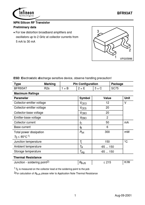
| Description | NPN Silicon RF Transistor |
| Category | Transistor |
| Manufacturer | Infineon |
| Size | 70.35 KB |
| Part Number | Manufacturer | Description |
|---|---|---|
| BFR93AT | NXP Semiconductors | NPN 5 GHz wideband transistor |
| BFR93A | NXP Semiconductors | NPN 6 GHz wideband transistor |
| BFR93AW | Vishay | Silicon NPN Planar RF Transistor |
| BFR93A | Vishay | Silicon NPN Planar RF Transistor |
| BFR93A | Siemens Semiconductor Group | NPN Silicon RF Transistor |