MRF175GU Overview
Key Features
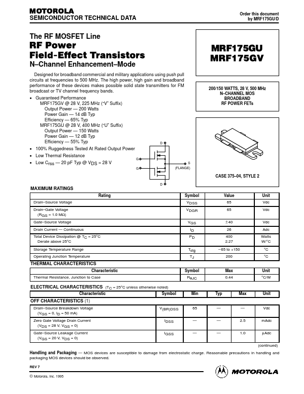
- Channel Enhancement
- Guaranteed Performance MRF175GV @ 28 V, 225 MHz (“V” Suffix) Output Power
| Part | MRF175GU |
|---|---|
| Description | N-CHANNEL MOS BROADBAND RF POWER FET |
| Manufacturer | Motorola Semiconductor |
| Size | 183.21 KB |
| Part Number | Manufacturer | Description |
|---|---|---|
| MRF175GU | Tyco Electronics | N-CHANNEL MOS BROADBAND RF POWER FET |
| MRF175GV | Tyco Electronics | N-CHANNEL MOS BROADBAND RF POWER FET |
| MRF175LU | Tyco Electronics | N-CHANNEL BROADBAND RF POWER FET |
| MRF175LV | Tyco Electronics | N-CHANNEL BROADBAND RF POWER FET |
| MRF173 | Tyco Electronics | N-CHANNEL BROADBAND RF POWER MOSFET |