Datasheet Details
| Part number | IRF1018EPbF |
|---|---|
| Manufacturer | International Rectifier |
| File Size | 425.89 KB |
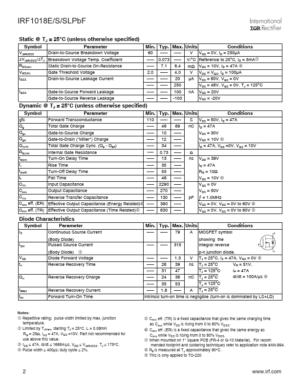
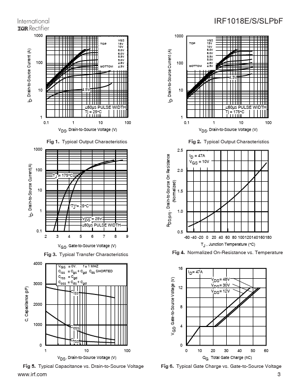
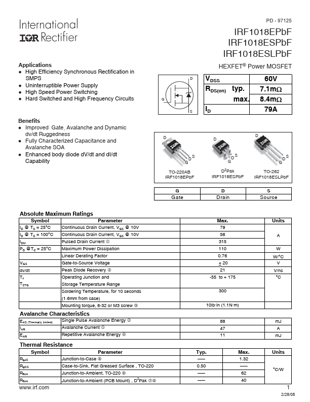
| Description | Power MOSFET |
| Datasheet |
 IRF1018EPbF Datasheet IRF1018EPbF Datasheet
|
|
|
| Part number | IRF1018EPbF |
|---|---|
| Manufacturer | International Rectifier |
| File Size | 425.89 KB |
| Description | Power MOSFET |
| Datasheet |
IRF1018EPbF Datasheet
|
|
|
|